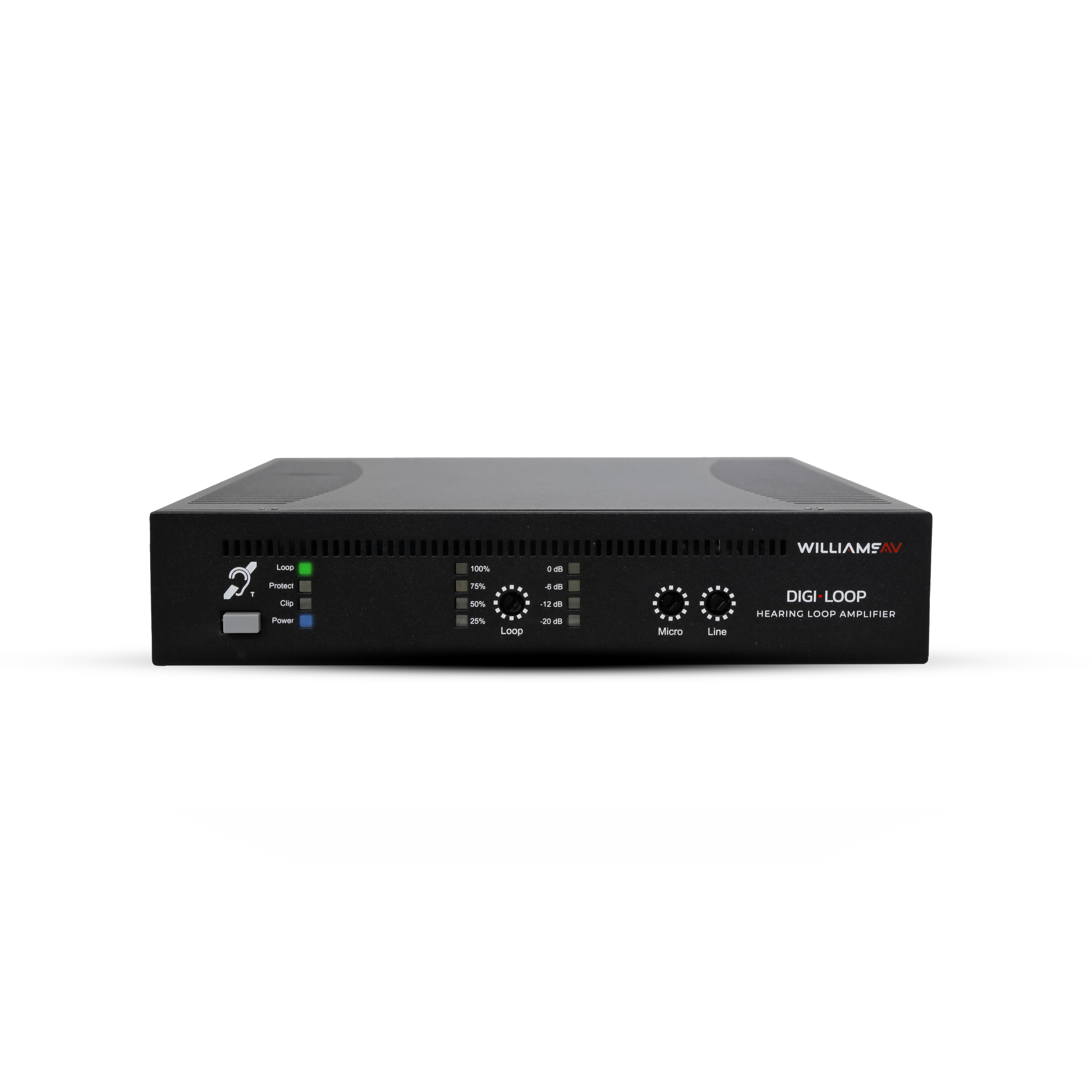
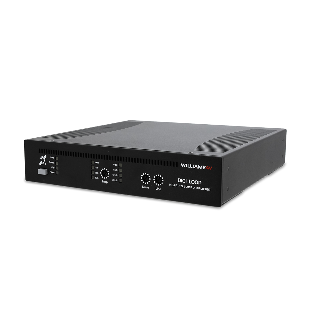
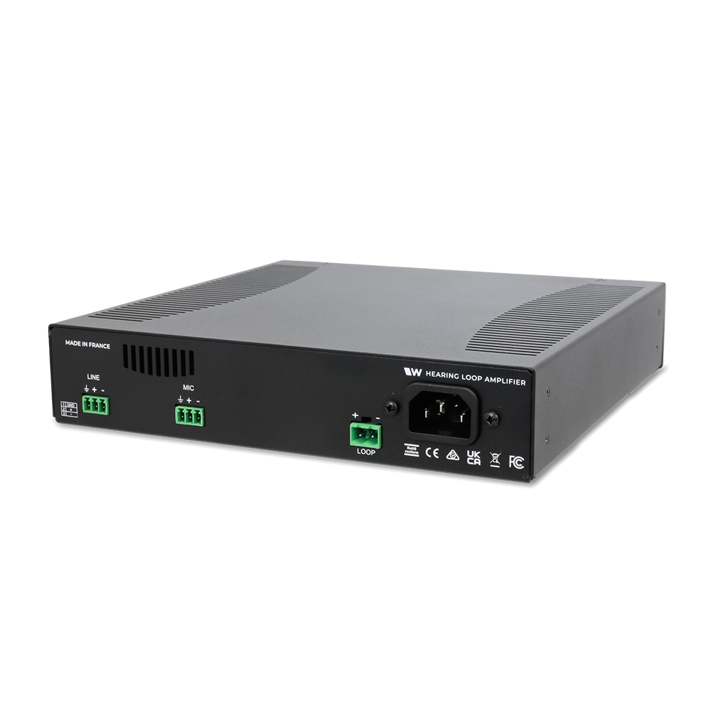
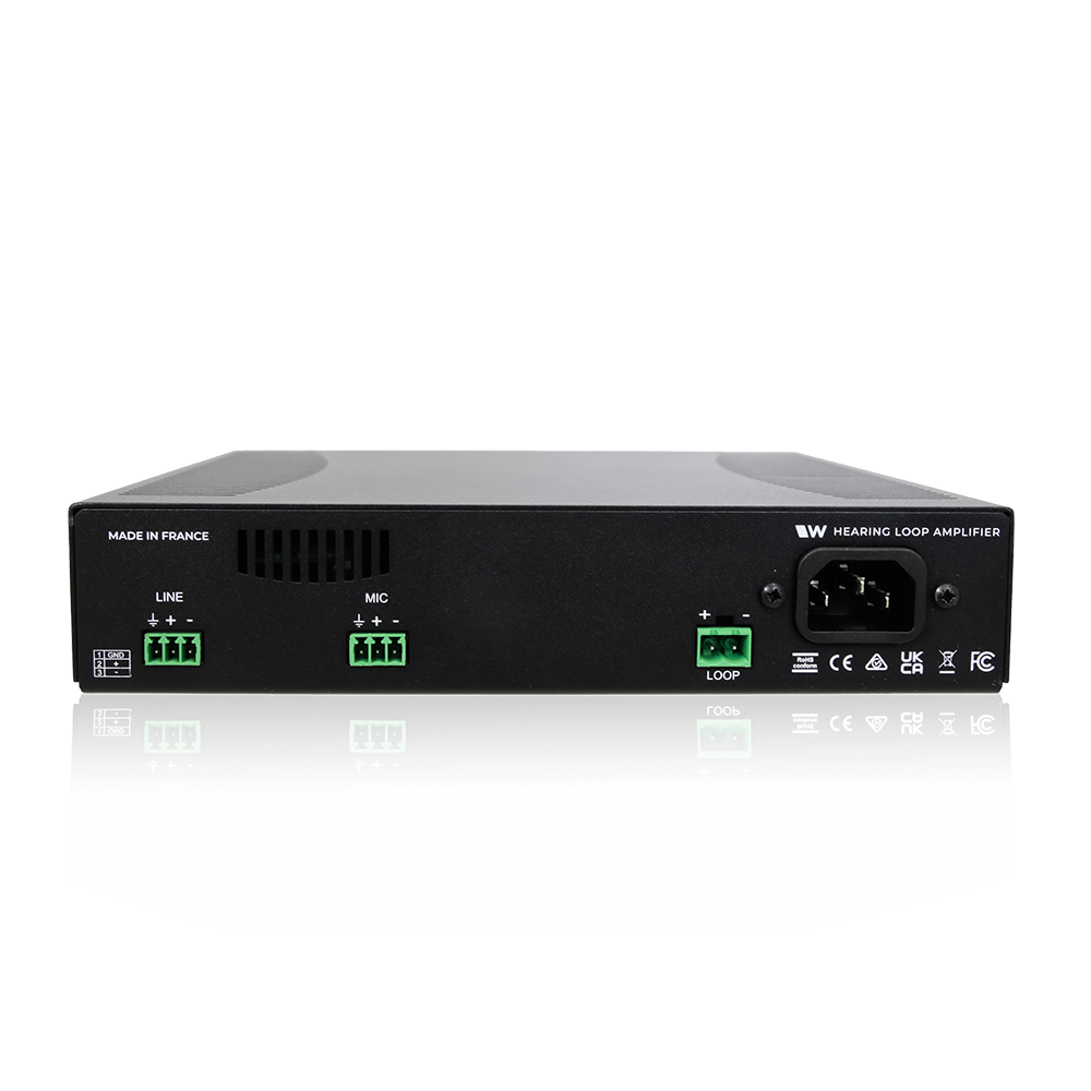
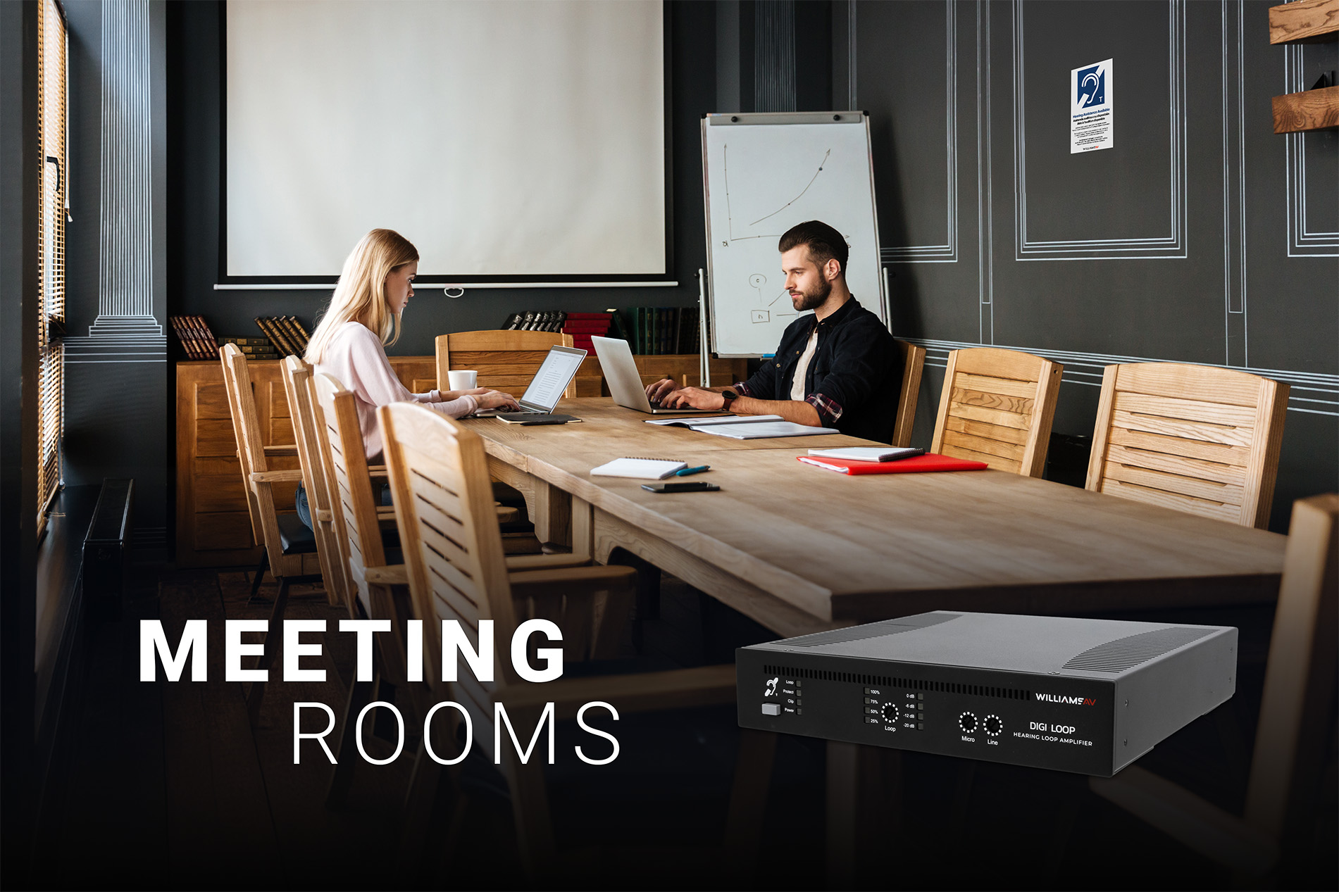
This single-channel, Class D perimeter hearing loop amplifier features high-efficiency technology for lower power consumption and natural cooling. Its compact design ensures it remains discreet in the venue, whether freestanding, wall-mounted, or rack-mounting. Designed with installers and venues in mind, it features easy input and signal adjustment, loop monitoring and fault detection, and a simple front panel. Automatic Gain Control (AGC) guarantees outstanding sound quality without clipping or distortion.
Digi-Loop products are feature-rich without the high price tag, making them ideal solutions for venues that want to make audio accessible to visitors without sacrificing quality. Why pay for product functionality your venue doesn’t need? The Digi-Loop 104 delivers high-quality sound in an easy-to-use and discreet form factor at a competitive price.
Want to learn more about hearing loops as an assistive listening system? Visit our Hearing Loops page to learn more about what is a hearing loop, different types of loops, how to implement a successful induction loop system, and more!
System Includes
- DL104 – Small Area Loop Amplifier
- Black Line Cord
- Set of 3 stickers with the T-coil icon
Features
- Loop coverage of up to 919ft² (250 m²) – max width : 32ft (10m)
- Advanced protection circuit helps maintain safe operating temperatures
- Inputs for microphone input or line input, balanced or unbalanced
- Meets CE certifications
- LED indicators
- Peak output current: 8A
- Standby mode
- Active protection against short and open circuits, clipping, and thermal (overheating).
- Meets ADA/ADAAG Guidelines
- 2-year Warranty
- Input level controls
- Loop output level control
- Single unit or dual units mountable in standard 19” rack (with optional rack mount kit)
How It Works
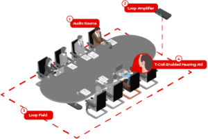 1. A sound source — such as a voice, TV, or other audio system — is captured using a microphone or via a line-out connection.
2. The sound signal is connected to the DL104 hearing loop amplifier. The amplifier generates a current to pass the signal to a hearing loop, usually made of copper tape or wire.
3. The copper wire hearing loop (usually) surrounds the area where the listening audience is located and produces a magnetic field.
4. The magnetic field is picked up by the T-coil inside the hearing aid, cochlear implant, or hearing loop receiver of an audience member with difficulty hearing. The hearing aid customizes sound to individual needs, delivering full-spectrum frequencies directly to the ear canal without background noise for improved intelligibility.
DL104 architectural and engineering specifications
Architectural/Consultant Specs DL 104
The hearing loop amplifier shall deliver 4 Arms output current and 34Vrms output voltage, with a peak output current of 8A. The unit shall have an integrated power supply of 230V (or 115V), with a power rating of 200VA. It shall be compatible with North America or international power systems when supplied with the appropriate power cord. The front panel shall include status LED’s that indicate when the power is ON labeled “Power” and when the loop is in proper working condition labeled “Loop”.
The hearing loop amplifier shall provide an output current adjustment screw and a separate LED output signal meter that indicates the percentage of full current in the induction loop. The hearing loop amplifier shall have one (1) standard loop output with a 2-position terminal block connection e.g. Phoenix style.
The hearing loop amplifier shall provide two (2) distinct audio input alternatives, Line-level and Mic-level. The Line-level input shall be a 3-position terminal block connection (Phoenix style). The Microphone-level input shall be a 3-position terminal block connection (Phoenix style).
The hearing loop amplifier shall provide a dedicated line input level adjustment screw and a dedicated microphone input level adjustment screw. The hearing loop amplifier shall provide an LED input signal meter to indicate the input signal level after adjustment.
The amplifier shall include fault detection and protection for when the loop amplifier is overloaded, the input level is too high, or the loop is defective. The front interface shall include an LED display labeled “Protect” and “Clip” indicating the amplifier is experiencing an error condition.
A single hearing loop amplifier shall mount in a standard 1 RU, 19” rack using ½ rack (with optional rack mount kit). Two (2) amplifies shall fit side by side into a standard 1 RU, 19” rack (with optional rack mount kit).
The unit shall meet IEC 60118-4 system performance requirements when the loop system is designed and installed correctly. Specifications/testing shall conform to IEC 62489-1 benchmark testing standards.
DL104
|
Dimensions:
|
1.7” x 7.8” x 8.5” (42mm x 200mm x 215mm)
|
|
Weight:
|
3.3 lbs (1.5 kg)
|
|
Operating Temperature Range
|
32 to 113 degrees F (0 to 45 degrees C)
|
|
Storage Temperature
|
-40 to 185 degrees F ( -40 to 85 degrees C)
|
|
Power Supply Type
|
Integrated
|
|
Power Supply Voltage
|
115/230 V (automatic) 50/60 Hz
|
|
Power Output
|
200VA
|
|
Power Consumption
|
6W
|
|
Nominal power consumption at 1 Ohm
|
50W
|
|
Maximum Input Power
|
500VA
|
|
Power consumption at rest with connected loop
|
14W at 230V AC, 2 loop of 1 Ohm connected, at ambient temperature after 30 minutes of stabilization.
|
| Mic Input (100V) |
(1x) 3-position terminal block (Phoenix)
|
| Microphone (100V) |
(1x) 3-position terminal block (Phoenix) |
| Power Supply |
12V 2mA |
| Input Sensitivity |
-50dB micro, +40dB 100V, -10dB line |
| Loop Integrity Indication |
Loop Impedance 0.5 – 3.0 Ohm |
| Loop Output |
(1x) 2-position terminal block (Phoenix) |
| Output Voltage |
34 Vrms (48 Vpk) |
| Output Peak Current |
8A |
| Output RMS Current |
4 Arms |
| Bandwidth |
80 Hz to 9.5 kHz |
| LED Display |
LED “Protect” light |
| Checking (synthesis fault) |
DC current too high – Open loop – Thermal protection |
| Cooling |
Natural cooling |
| IP Rating |
IP 20 |
| Frequency Response |
40 Hz to 9.0 kHz |
Warranty
2 Years
 1. A sound source — such as a voice, TV, or other audio system — is captured using a microphone or via a line-out connection.
